In two previous articles we’ve explored interrupt latency on the ARM Cortex-A. While the numbers in those articles were measured using synthetic benchmarks, real application results are usually more useful. However measuring interrupt latency directly can be quite invasive and difficult since it involves accessing a hardware timer and also designing a method to detect the moment an interrupt become active. This article shows a simple way of measuring, or more precisely estimating, the worst case interrupt response time in a running application, which can be implemented on most MCUs and RTOSes or even in bare-metal. All that is needed is a hardware timer that can generate an interrupt after an arbitrary time delay. The technique is also rather non-intrusive, making it usable all the way to production without significantly affecting the application’s performance.
The idea of using a counter is to ensure that the interrupt firing point is totally independent of the application, especially if running under an RTOS. If instead of a timer, an interrupt is triggered by software from a task then the trigger point then the interrupt is always generated roughly from the same system state. This has the disadvantages of introducing bias in the interrupt latency sampling and also consumes additional resources for a task and its stack.
Sampling ISR
The easiest way to implement the sampling method is to use a free-running counter that supports a compare and match interrupt. While possible with an auto-reload interval counter, it is trickier. In either case, the interrupt should be set up to fire on a running timer, the initial delay value should be far enough in the future not to be affected by the setup procedure, but the exact value of the initial delay is otherwise not very important.
Once fired, the sampling and update of the timer compare value should be done from within the Interrupt Service Routine (ISR) for maximum efficiency.
In pseudo-code the sampling ISR would look something like this.
// Query the current timer value as soon as possible.
current_count = timer_count_get();

// Subtract the current_count from the target_count. If everything is handled correctly and the timer
// frequency is high enough, current_count should always be higher than target_count.
latency = current_count – target_count;

// Keep track of the latency as needed. For example, it’s possible to keep track of the minimum and
// maximum interrupt latency as well as keep a running average of the interrupt latency.
tally_latency_stats(latency);

// Generate a random value, see text for additional details on the random value.
next_delay = rand();

// Clear or acknowledge the match interrupt as needed by the hardware timer.
clear_timer_interrupt();

// Reset the match interrupt to the current_count value + next_delay.
timer_match_set(current_count + next_delay);

// ISR end.
The random delay
The generation of the random delay value is very important. The primary reasons for using a random value instead of a fixed sample frequency are twofold. First, it prevents issues with sampling periodic behaviours that might affect interrupt latency. Especially when running under an RTOS, a lot of events are triggered by the RTOS ticks, meaning that a lot happens at the start of a millisecond, creating a periodic component in the CPU usage. A random sampling values ensure that the results are not affected by a periodic event. The second reason for using a random delay between sample is to capture the effect of time from the last interrupt on the interrupt response time. Especially for a CPU with caches, the longer it’s been since the last interrupt, usually the higher the average latency due to cache misses.
The exact range of delays is dependent on the application. Higher sampling frequency will increase the accuracy of the worst case latency estimation, since it increases the chance of sampling at the worst possible moment. However too high a sampling frequency could affect the application performance. On the other hand, too low a sampling frequency reduces the chances of capturing the worst case event, meaning it’s a tradeoff between the quality of the sampling and performance.
When generating a random number the C rand() function may be usable but care should be taken that it is safe to call from an interrupt. It must not be too computationally heavy, and must not attempt to acquire a kernel mutex. For example, some thread-safe C libraries might use a kernel mutex to enforce thread safety, which won’t work from an ISR. Either way, a simple LCG generator can be written in two to three lines of code and is perfect for our needs.
Once a random value is generated, it must be scaled to a range of values suitable for the sampling delay. Here again, speed and simplicity is better than trying to be fancy, as such, simply discarding bits from the generated result to bring the maximum delay within an acceptable range is recommended. Also remember that when taking bits from a LCG generator it is preferable to keep the top bits and discard the lower end bits. Finally, it is advisable to add an offset to the generated value to ensure a minimum delay. The minimum delay should be at least the minimum interrupt response time and ideally a few times the average interrupt response time.
Interrupt configuration and sampling point
When registering the interrupt, it should be of the same type as the class of interrupts we want to sample. For example, on a platform with both maskable or non-maskable interrupts, if we are interested in the non-maskable interrupt response time, the timer ISR should also be non-maskable. Same goes with the interrupt priority. This is a rather versatile aspect of this measurement method where it’s possible to look at exactly the type of interrupt we are interested in.
The sampling point, which is where the current timer value is read within the interrupt, should usually be as early as possible to discard any additional overhead from the samples. However, if the response time of a specific action to be performed within the ISR is important, then the sample can be taken after performing a similar action in the sampling ISR. For example, let’s say that the critical action to be taken is to toggle a GPIO in response to a specific interrupt, our ISR could toggle another, unused GPIO prior to reading the counter value.
Some results
The exact results returned by this method are highly dependent on the platform and application. A useful starting point is to measure an idle system vs a fully running system. For example, here I’ve measured two sets of interrupt latency on a 600 MHz CPU running an RTOS. For the purposes of the discussion, the results are plotted on a normalized histogram. Note the log scale in use on the Y axis.
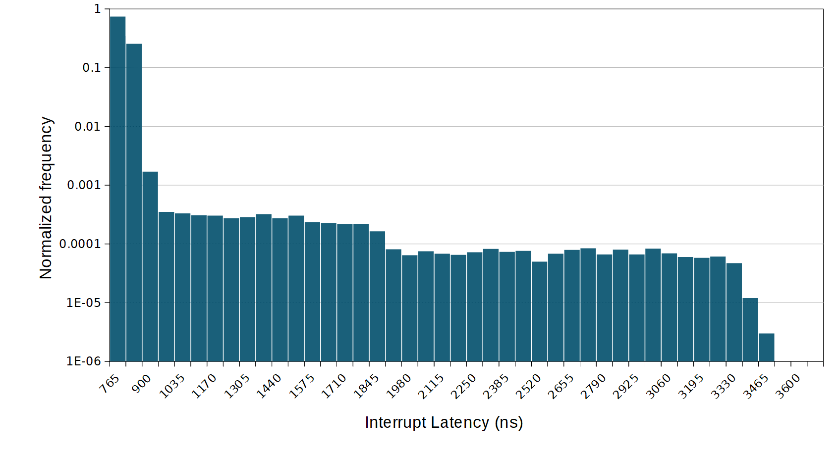
In this first graph, we have the idle interrupt latency distribution. This is relatively typical of an idle RTOS. Most of the interrupt are very quick, around 700 ns, while a very few outliers go up to around 3.9 us. The higher end of the range in this case is the effect of the kernel tick and timer processing, while quick in an idle application, still disables the interrupts for a certain amount of time. The random sampling allows us to capture the relatively rare event where can interrupt fires during tick processing.
Now, running a random memory benchmark while sampling interrupt response time.
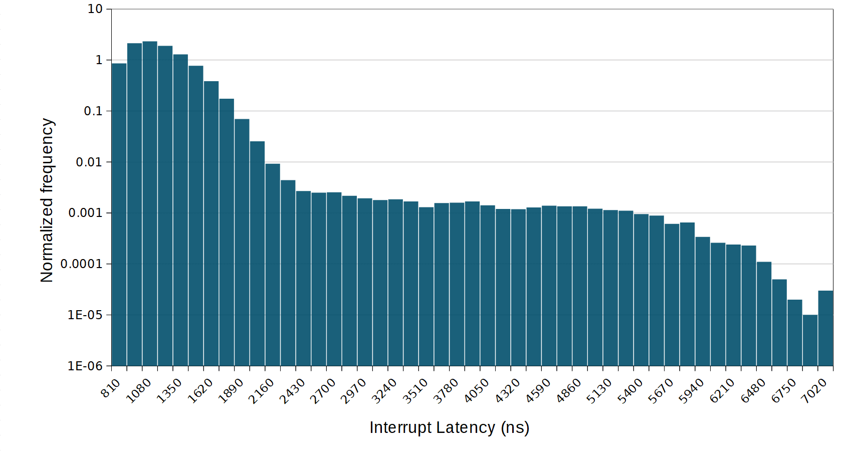
Here we can see that the average response time as increased considerably along with the worst case interrupt response time. This is congruent with the effect of the memory accesses on the cache hierarchy. This is similar to the effect measured in a previous article.
What now
The interpretation of the results could probably be the subject of multiple articles. But in general two questions are important. First, if the application has a requirement for a certain interrupt response time the measured maximum interrupt response time should be below that value. If the maximum is over or close to the maximum then it is fair to say with confidence that timing won’t be met at runtime.
The second question to ask is if the measured numbers are reasonable. Even if the application has no real time requirements with respect to interrupt latency, an unusually long interrupt response time could affect performance and reliability of the application. In extreme cases, very long interrupt latency could be indicative of a software bug or design issue which should be addressed.
Questions or comments?
Do not hesitate to contact us at blog@jblopen.com. Your questions, comments and, suggestions are appreciated.