Continuing from the last post, this article explores features specific to early members of the ARM Cortex-A family such as the Cortex-A9 which can help reduce interrupt latency. Namely the L2 cache and TLB lockdown features found in those processors. It’s important to note that those two features are not available in more recent 32 and 64 bits ARM processors such as the Cortex-A7. Newer cores have a simpler TLB, and most often than not an integrated L2 cache instead of the external L2 found on the A9. However, the Cortex-A9 is still a popular core, found on the Xilinx Zynq-7000 and NXP i.MX 6 SoCs to name a few.
In theory, cache lockdown or isolation, prevents other data and instructions from taking the place of critical code and data. TLB lockdown, on the other hand, prevents TLB misses on those same areas. When asked about those features, and if they can help improve interrupt latency in a customer’s application, it’s often hard to put numbers to back the discussion. Worst case interrupt latency is very application specific and consequently, the effect of cache lockdown depends a lot on the application layout and memory access patterns.
However, in this article, I’ll attempt to demonstrate how it works and what can be achieved using a synthetic workload.
Testing interrupt latency
The test is relatively simple and consists of performing a random number of (random) data and instruction accesses and then triggering an interrupt. Measuring the time between the trigger and the interrupts gives a distribution of interrupt latency. This method of measuring interrupt latency is explained in details in another article. Everything is done with a minimal bare metal environment to minimize the effect of code and data outside of our interests. The results would be very similar with an efficient RTOS.
This is the result of 2 million iterations without any lockdown.
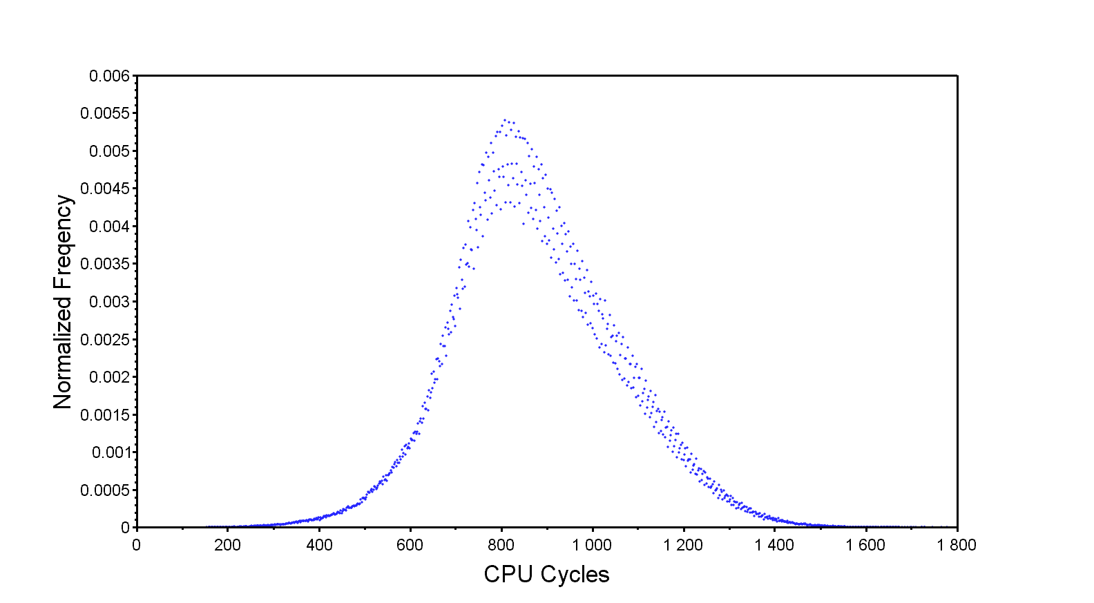
The distribution is relatively wide and bell shaped, which isn’t surprising considering the random nature of the input. The overall response time is rather good, an average of 876 cycles and the fastest response time at 154 cycles. Most importantly, however, is the worst case, which is far to the right at 1778 cycles and very infrequent, happening once in 2 million iterations. It’s this worst case that we are trying to improve.
TLB lockdown
The Translation Lookaside Buffer or TLB for short is a specialized cache used by modern processors that have a Memory Management Unit (MMU). The MMU is responsible of performing virtual to physical memory address translation as well as permission checking for every memory access done by the CPU core. The MMU will use a more or less complex page table in memory to perform the translation. A translation, known as a page table walk, is a rather long operation that can consist of multiple access to main memory. To improve the performance of modern CPU the TLB is used to store recently used translation results.
The main TLB of a Cortex-A9 consists of 64 to 512 2-way set associative entries plus an additional four fully associative and lockable entries. Those lockable entries can be filled and then locked in software in order to prevent them from being replaced automatically. The goal, is to lock those four entries to cover everything in the critical path of an interrupt processing. This includes the ISR itself, the kernel or bare metal interrupt handling functions and data as well as any data and peripherals accessed by the ISR.
For this demonstration, the translation table is using 1 MiB sections, as such the four entries can hold four 1 MiB regions of the full address space. Since this is a small bare-metal application all the code and data, and the accessed peripherals, can be locked in the four available entries. Not forgetting, of course, the private peripheral region where the GIC and global timer are located.
And this is the result.
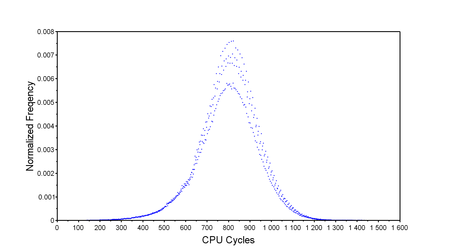
This shows an improvement of a few hundred cycles to the maximum latency. With that said, TLB lockdown might be a bit overkill for a bare metal or a compact RTOS application. For example, on the Zynq-7000 the main TLB can hold 128 entries, effectively mapping 128MiB of address space when using 1MiB sections for the translation table. Using 16MiB super-sections instead will increase that to 2GiB which makes locking relatively inconsequential. However, latency critical applications could lock 1 or 16MiB regions anyway to absolutely guarantee that those entries are held in the TLB.
Cache lockdown
Cache lockdown is a feature of the PL310 (Later renamed L2C310 at revision r3p0) L2 cache controller often found in Cortex-A9 based SoCs. This feature allows entire cache ways to be locked to prevent them from being evicted. It’s somewhat trickier to use but makes the locked code access time very deterministic.
Combining the TLB and cache lockdown give a considerably different result.
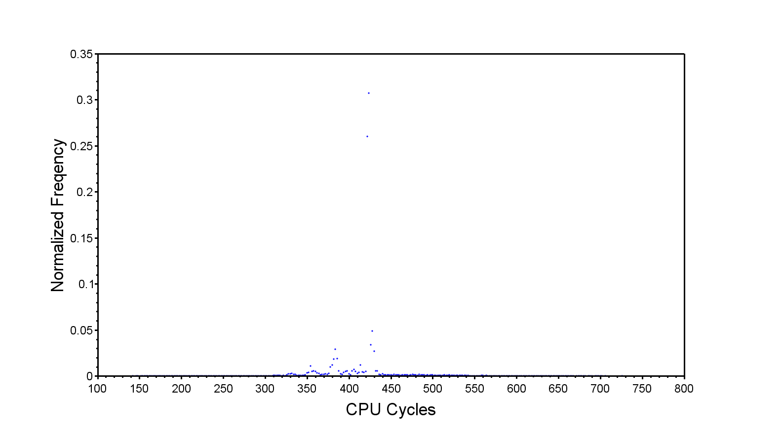
Worst case latency is a little more than half-way from where we started. I’m assuming the long trailing edge to the right of the distribution is due to a small portion of code or data not being locked for some reason. It may also be due to various states of the L1 level but I doubt it.
Downsides
Nothing is free, however, and both methods have a cost. They both lock cache resources on possibly seldom used code and data. This reduces cache efficiency and overall performance.
First the TLB lockdown reduce the overall available TLB size. However, considering the generous size of the TLB this is a non-issue for most embedded applications. It’s important to note that TLB performance is critical to most ARM processors, as they generally have a physically indexed L1 data cache, meaning a cache lookup cannot start before a TLB result is available. Also, the main TLB has only 2-way associativity, while the four lockable entries are fully associative. Those four entries may help with some memory access patterns.
On the L2 lockdown side, obviously locking full ways will result in a significantly smaller L2 cache area. Again, most embedded applications tend to be very cache efficient so this may not make a measurable difference. Even so, since cache ways are locked this effectively reduces associativity possibly generating more cache trashing and increasing pressure on the main memory.
What else?
Finally, other methods, are available to help with interrupt response time. Usually by placing critical code and data in on-chip ram. Luckily, while newer SoC do not have lockdown options they tend to have more generous internal ram.
Click here to read our article on how to estimate worst case interrupt latency in an embedded application.
Questions or comments?
Do not hesitate to contact us at blog@jblopen.com. Your questions, comments and, suggestions are appreciated.