This article will go over some aspects of the early bring-up experience using the BASEplatform™ on the Toradex Colibri iMX7 System on Module (SoM). It will also cover features and advantages of the Colibri SoM for embedded developers interested in using an RTOS or a bare-metal environment on the NXP i.MX7 SoC.
The BASEplatform is a collection of embedded software components designed to provide application developers with all the necessary software modules, BSP, drivers and RTOS integration needed to jump start their embedded software project. In the case of the i.MX 7, the BASEplatform’s drivers and BSPs supports both the Cortex-A7 and Cortex-M4 cores using either an RTOS or bare-metal. The API is portable between both cores and between different RTOSes making it very flexible. This enables developers to select the best combination of software environments on both cores.
Let’s talk about the hardware, the Toradex Colibri is a series of System on Module using a compact form factor coupled with an SODIMM connector. The SoM board contains all the necessary components for the basis of an embedded system. There are a few different SoC options, but the one we are interested in today includes the NXP i.MX 7 SoC, DDR RAM, flash storage, power management unit, and more.
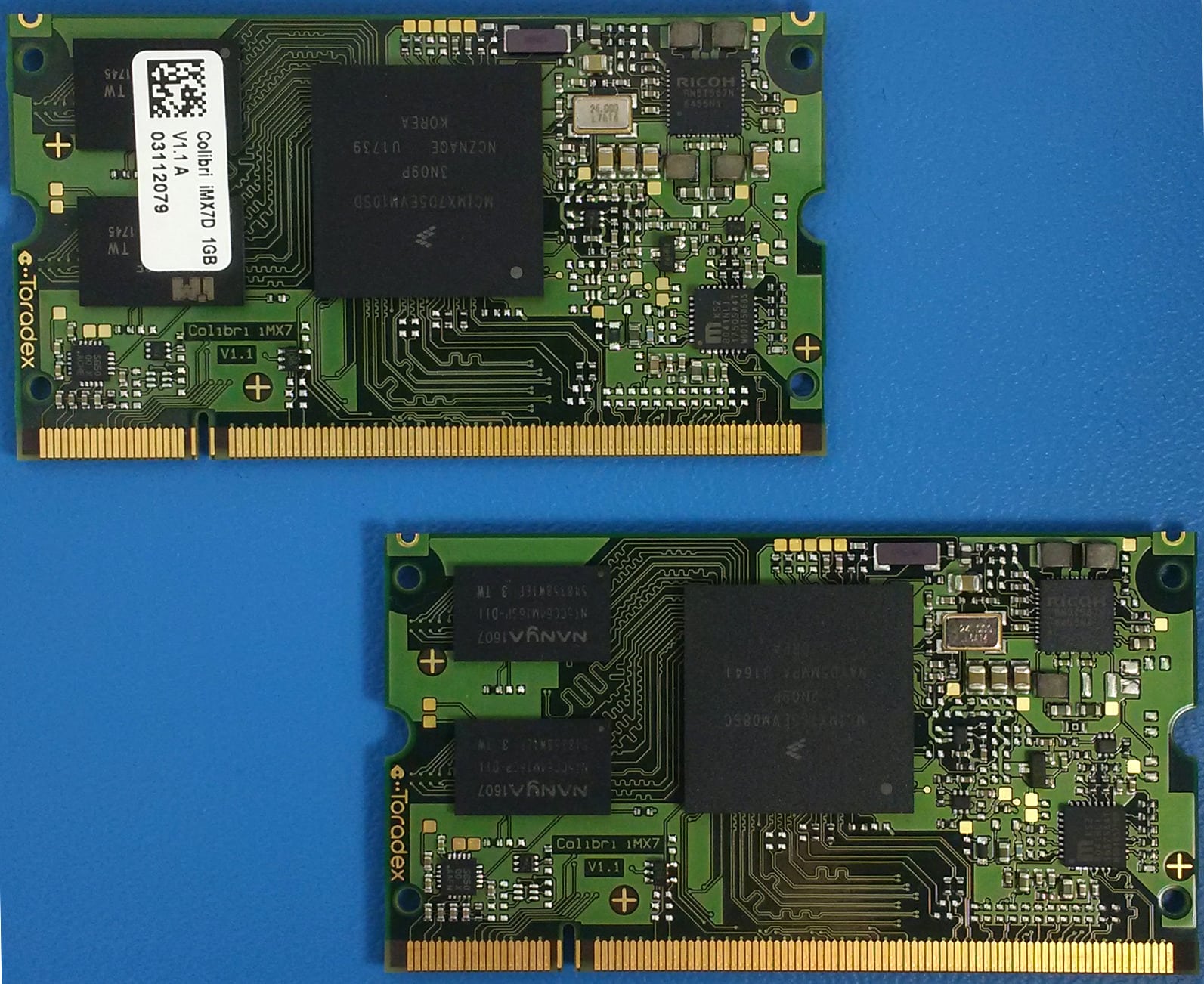
The modules are designed to be coupled with a carrier board which provides external connectors, additional peripherals and main power to the SoM. Toradex provides a selection of prototyping carrier boards and the Colibri Evaluation Board is used for this demonstration.
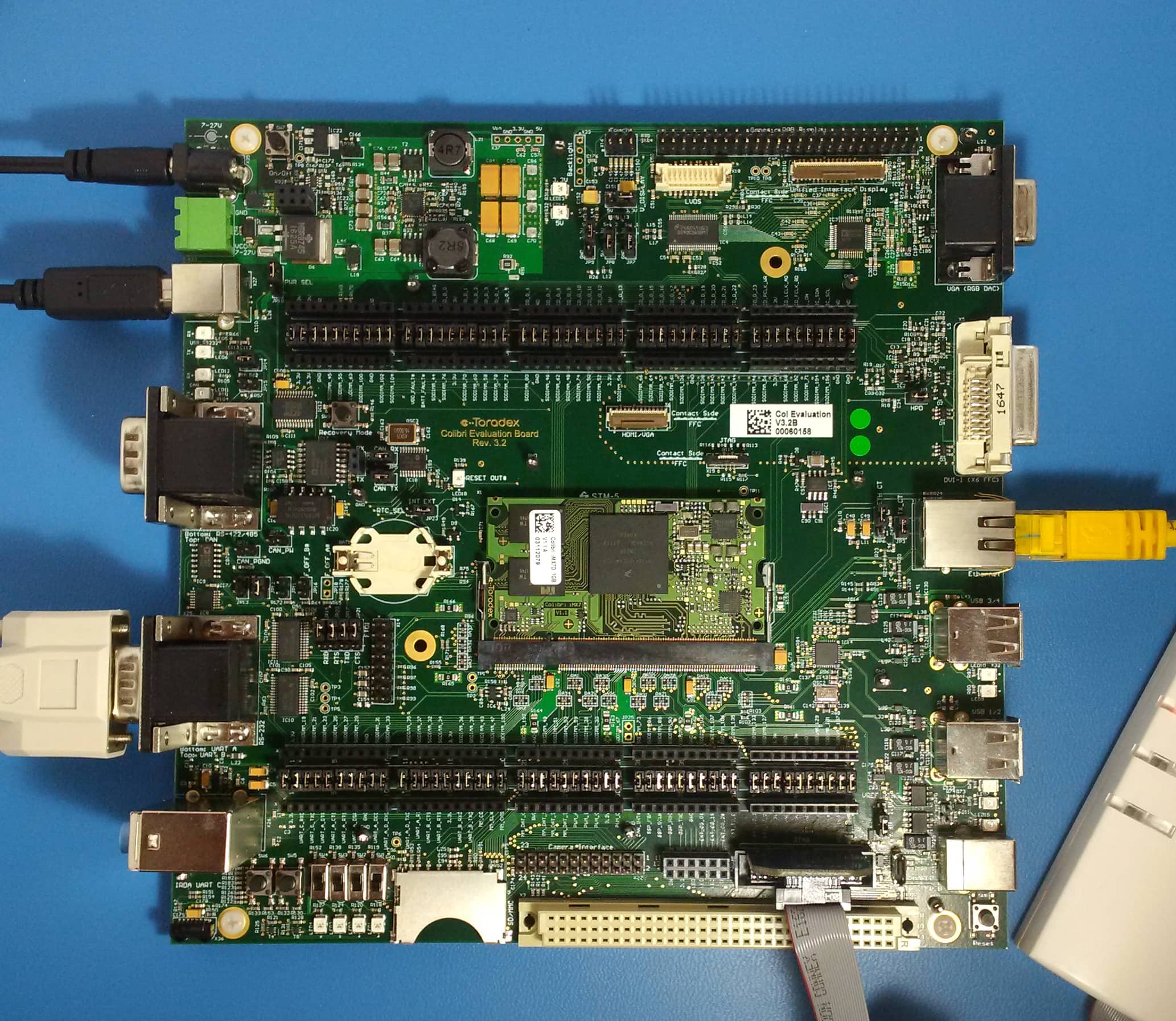
The Colibri Evaluation Board is everything one can dream of when it comes to early prototyping, it has an enormous number of features but is nonetheless very flexible. From the point of view of a developer who ports RTOSes and writes drivers and BSPs the evaluation board is perfect. It comes loaded with a variety of peripherals and connectors, but at the same time nearly all of the I/Os are accessible and can even be disconnected from their pre-assigned connector. This is very useful compared to many reference designs and demonstration boards which are often so loaded with features that it’s difficult to find enough free I/Os to perform testing and validation of low-level drivers.
Also there is one little feature, often disregarded on many boards, that deserves a paragraph. The carrier board has a dedicated recovery mode button, which is usually pressed to recover from a corrupted or incorrect boot image. When debugging through JTAG however, it means that it’s possible override the boot mode with the push of a button, very useful when debugging a bootloader or a flashed application. It allows the developer to load an application image into RAM using JTAG without having to change the boot switches or jumpers every time.
BASEplatform
The BASEplatform, as its name might suggest, takes care of all the low level initialization, peripheral modules and drivers as well as RTOS integration to enable application developers to jump directly to application development. For demonstrations, we’ll show how easy it is to create a UART interface for a simple hello world type of example that is compatible with both the A7 and M4, as well as how the BASEplatform can handle external board components such as the RN5T467 PMU found on the Colibri SoM.
But first there is one more feature of the Toradex ecosystem that warrants mention, the Toradex Pinout Designer. When creating a board support package for the BASEplatform we often write the pin mux configuration by hand. This allows us to fine-tune the default pin configuration and ensures that the default configuration will work out of the box when in the customer’s hands. Developers can then elect to either continue tweaking the pin configuration by hand or use the various pin tools provided by most semiconductor manufacturers.
Toradex provides the pinout design tool that helps board designers with the selection of pin functions that can be assigned to the SoM connector’s signals. It also facilitate migration from one module to the next since many of Toradex’s SoM are pin compatible. This tool, as we found, is very useful when configuring the pin mux programatically as well. First you select the module, peripheral functions and mapping and then the entire configuration can be exported to a spreadsheet. This spreadsheet contains all the signal names, SoC pads and necessary alternate functions that must be set in the pin mux configuration. All in all, a great time savers that also reduces annoying to debug pin mux configuration errors.
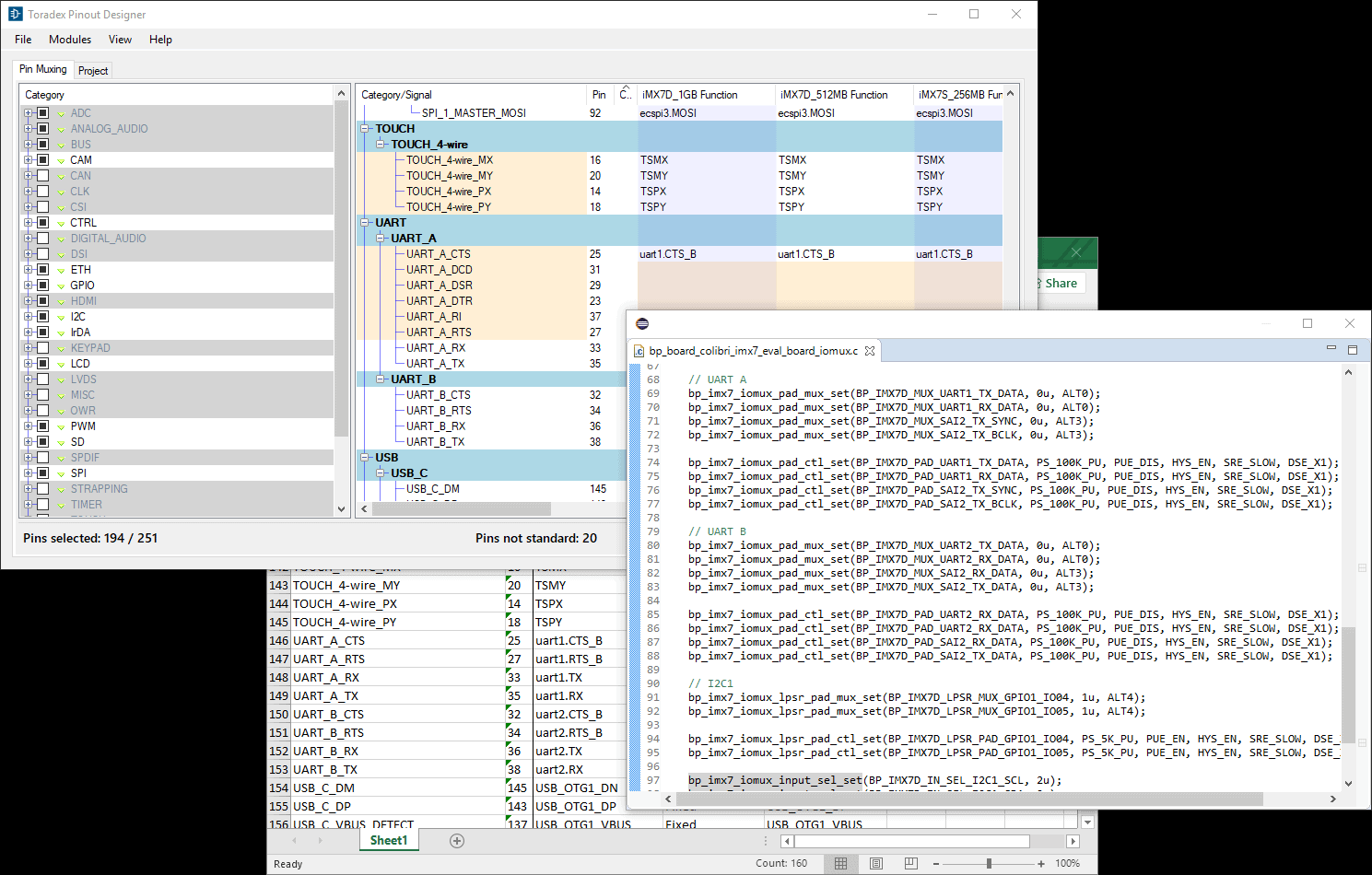
Returning to our hello world example, here’s an example of the UART pin configuration for UART A of the Colibri Carrier Board. Note that error handling is omitted from these snippets of code for clarity.
bp_imx7_iomux_pad_mux_set(BP_IMX7D_MUX_UART1_TX_DATA, 0u, ALT0);
bp_imx7_iomux_pad_mux_set(BP_IMX7D_MUX_UART1_RX_DATA, 0u, ALT0);
bp_imx7_iomux_pad_mux_set(BP_IMX7D_MUX_SAI2_TX_SYNC, 0u, ALT3);
bp_imx7_iomux_pad_mux_set(BP_IMX7D_MUX_SAI2_TX_BCLK, 0u, ALT3);

bp_imx7_iomux_pad_ctl_set(BP_IMX7D_PAD_UART1_TX_DATA, PS_100K_PU, PUE_DIS, HYS_EN, SRE_SLOW, DSE_X1);
bp_imx7_iomux_pad_ctl_set(BP_IMX7D_PAD_UART1_RX_DATA, PS_100K_PU, PUE_DIS, HYS_EN, SRE_SLOW, DSE_X1);
bp_imx7_iomux_pad_ctl_set(BP_IMX7D_PAD_SAI2_TX_SYNC, PS_100K_PU, PUE_DIS, HYS_EN, SRE_SLOW, DSE_X1);
bp_imx7_iomux_pad_ctl_set(BP_IMX7D_PAD_SAI2_TX_BCLK, PS_100K_PU, PUE_DIS, HYS_EN, SRE_SLOW, DSE_X1);
The BASEplatform has a modular architecture with modules instantiated at runtime. This allows for maximum flexibility, and in the case of the Colibri module, enables supporting more than one carrier board with the same firmware. Initialization of the SoC, CPU core, C library and RTOS is taken care of by the BASEplatform init code. The configurations necessary for all the supported SoC peripherals are also delivered with the BASEplatform, this includes clock, reset and interrupt routing.
To open a UART interface, in this example UART A of the carrier board, we can directly call the create function, configure the UART and enable it. As an added twist, the carrier board uses the DTE(Data Terminal Equipment) mode to wire the UART pins. This means that by default, the rx/tx and cts/rts pins will be reversed, changing mode requires the use of a driver specific API, since this isn’t a standard feature on most UART peripherals. This can be accomplished using the BASEplatform extended driver API which provides additional API calls specific to each driver, in this case bp_imx_uart_dcedte_set() to switch the DCE/DTE mode of the i.MX UART.
bp_uart_hndl_t uart_hndl;
bp_uart_drv_hndl_t drv_hndl;
bp_uart_cfg_t uart_cfg;

uart_cfg.baud_rate = 115200;
uart_cfg.parity = BP_UART_PARITY_NONE;
uart_cfg.stop_bits = BP_UART_STOP_BITS_1;

bp_uart_create(&g_colibri_imx7_eval_uartb, &uart_hndl);

bp_uart_cfg_set(uart_hndl, &uart_cfg, TIMEOUT_INF);

bp_uart_enable(uart_hndl, TIMEOUT_INF);

bp_uart_drv_hndl_get(uart_hndl, &drv_hndl);

bp_imx_uart_dcedte_set(drv_hndl, BP_IMX_UART_DRV_DCEDTE_DTE);
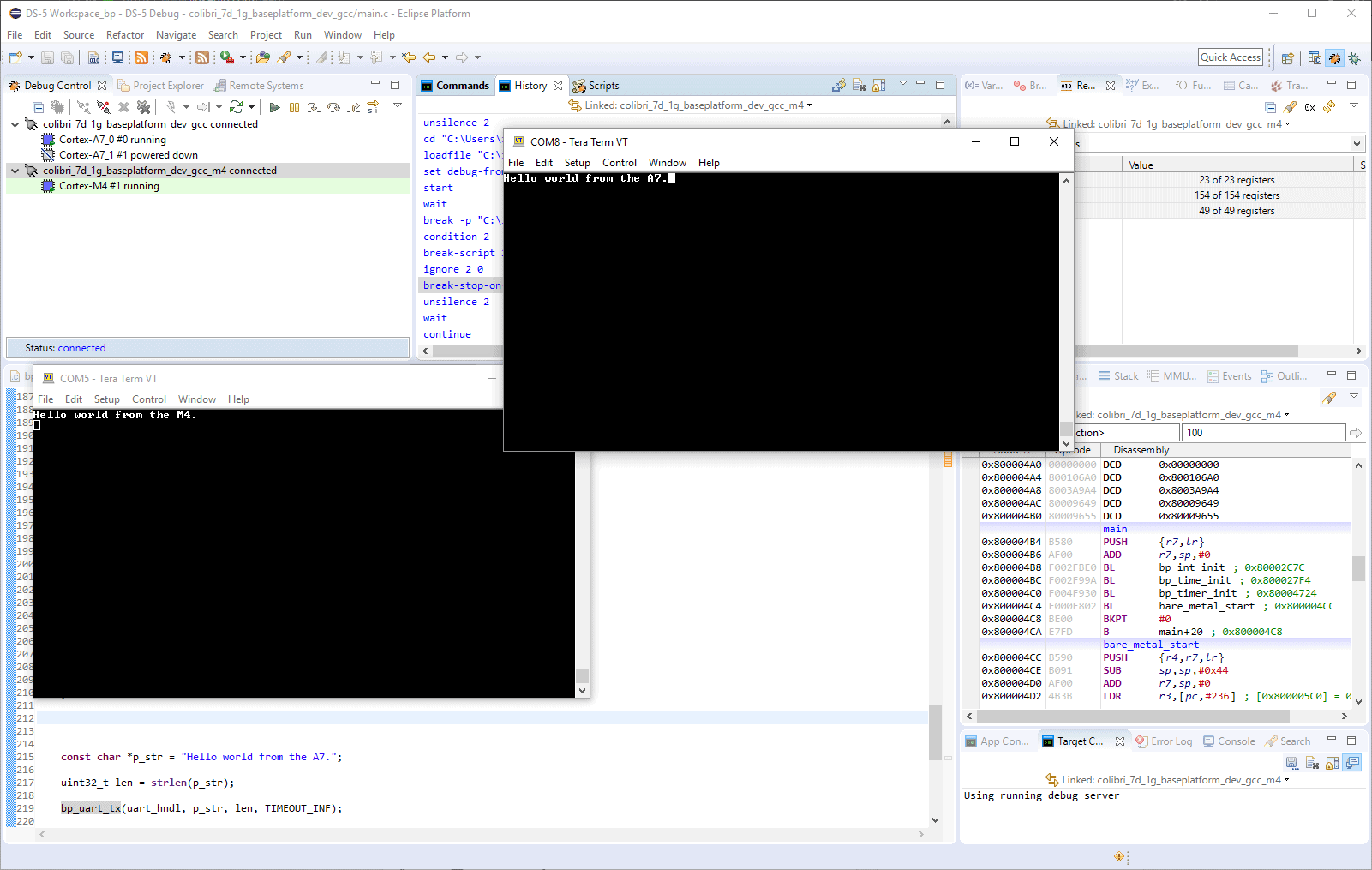
The UART is now ready to use, and as promised the classic hello world.
const char *p_str = "Hello world from the A7.";
uint32_t len = strlen(p_str);
bp_uart_tx(uart_hndl, p_str, len, TIMEOUT_INF);
At the risk of repeating myself the aforementioned API is portable between the A7 and M4. So this is really a heterogeneous multicore hello world.
In contrast to the standard peripheral modules, SoC specific modules usually have a simpler API and can be called directly instead of being instantiated.
For example, to query the A7 core clock speed:
uint32_t clk_freq;
bp_ccm_clock_freq_get(BP_IMX7_CLK_ARM_A7, &clk_freq);
or disable the USB HSIC LDO:
bp_imx_pmu_ldo_dis(BP_PMU_LDO_1P2);
Also, as mentioned earlier, the BASEplatform integration doesn’t stop at the SoC’s boundary. External components can be added and integrates well with the other BASEplatform module. For example, the RN5T567 PMU found on the Colibri SoM requires an I2C peripheral, which can be created pretty much the same way as the UART example. While it would be perfectly possible to interact with the PMU by doing I2C transfers directly, the BASEplatform includes a board component module specifically for the RN5T567.
bp_rn5t567_create(&g_colibri_imx7_pmu, &pmu_hndl);

bp_rn5t567_lsi_ver_read(pmu_hndl, &ver);
That’s about it for this article, if you want to know more about the Toradex Colibri i.MX 7, please visit the Toradex website.
To learn more about the BASEplatform take a look at the product page: www.jblopen.com/baseplatform/
Questions or comments?
Do not hesitate to contact us at blog@jblopen.com. Your questions, comments and, suggestions are appreciated.