This is part 2 (Click here for part 1) of a series of articles discussing the configuration of the Xilinx MicroBlaze soft CPU core when targeting an RTOS application. This series focuses on the software aspects of the MicroBlaze configuration and the impact of the various MicroBlaze configurations on an embedded application running under an RTOS. This article aims at helping developers and designers who must configure a MicroBlaze system. Especially early on in the development process where the final firmware is not available for benchmarking and tweaking. At these early steps it is often necessary to select a good approximation of the final configuration to have a good idea of the resource usage of the MicroBlaze.
This article will go into some details over the numerous configuration options available to the MicroBlaze. However, in order to keep the length of the article manageable, the cache configuration aspect will be left to be covered by a future article.
The Advanced Button
When opening the MicroBlaze configuration in Vivado you are greeted with the MicroBlaze Configuration Wizard. However, more importantly, is the “Advanced” button around the top left corner that is just begging to be clicked. Without pressing the Advanced button, the developer has the choice of various presets tailored for different implementation targets or application types. This article will obviously go over the Advanced configuration instead of the presets but before going over the Advanced configuration there are a few things to say about the first panel of the Configuration Wizard.
The MicroBlaze Configuration Wizard
There are three items to discuss about the first pane of the configuration, especially which configuration to start with as some options are not accessible under some configurations which can be confusing later on.
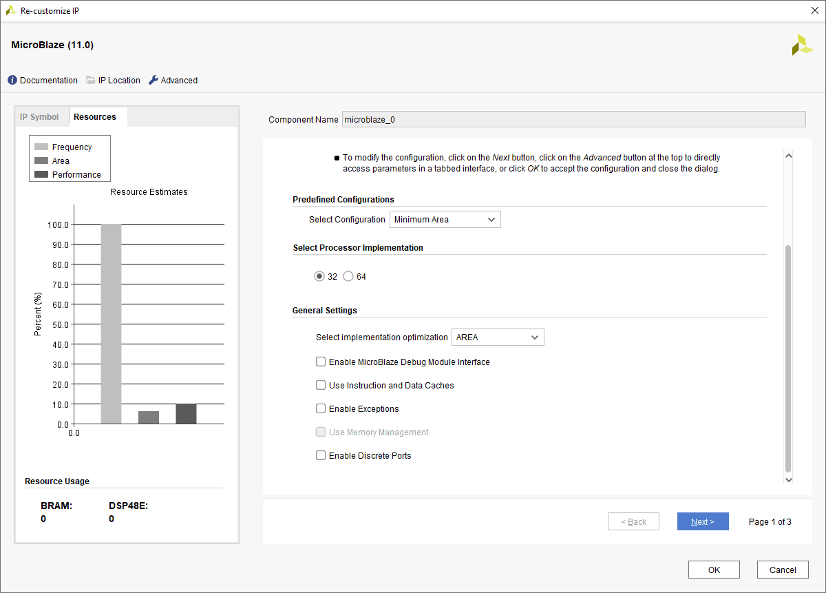
Predefined Configurations
As the name suggests, the predefined configurations offer a selection of presets that are either tailored for a type of application, for example the “Microcontroller” or “Real-Time” presets, or tries to optimize a particular implementation characteristic, for example “Maximum Frequency” or “Minimum Area”. Care should be taken as selecting a preset will override many of the other configurations. Before going into the advanced configuration, it is recommended to select “Minimum Area” which will give a very minimal MicroBlaze configuration to start with.
32 or 64 Bit MicroBlaze
Around the end of 2018, Xilinx very stealthily released a 64-bit version of the MicroBlaze. In 64 bit the MicroBlaze registers are extended to 64 bits and the processor address space is also considerably expanded. Note that the MicroBlaze could support address extension so was able to address more than 4 GiB of data before in certain configurations. From the point of an RTOS application, 64 bit support is rather situational, especially if there is a need to address more than 4 GiB of data. It is important to note that compared to certain other CPU architecture where their 64-bit counterpart had considerably higher performance this is not usually the case for RISC processors. On the one hand, the CPU performance is improved when handling 64 bit data types, however pointers are now wider increasing bandwidth usage and slightly reducing cache efficiency. The 64-bit implementation also increases the FPGA resource usage and can slightly reduce the maximum achievable frequency along with a small increase in power usage. When using an RTOS the 64-bit implementation is probably reserved for applications that require the extra address space or can benefit considerably from wider registers.
Note that there is no way in the current version of Vivado (2018.3) to select the 64-bit implementation from the Advanced configuration dialogs. As such this selection should be done now before we continue.
Implementation Optimization
The “Select implementation optimization” selection box is also available in the advanced configuration but being one of the most important setting it is covered now. It’s also a rather confusing configuration at first, but Xilinx improved the documentation considerably in recent releases with respect to this configuration. Simply put this configuration selects which implementation of the MicroBlaze pipeline is used to maximize either resource usage, overall performance or maximum frequency. It also affects the availability of other configurations, especially with “Area” optimization where many features become unavailable.
Area Optimization
With Area optimization, the MicroBlaze is implemented using a three-stage pipeline to minimize resource usage at the cost of overall processor performance. Many features, such as caching and branch prediction are not compatible with area optimization. Other than the obvious choice of minimizing FPGA resource usage, Area Optimization is also a good choice for simple applications, using and RTOS or not, that runs entirely out of local memory. In this situation caches are not required and branch misprediction penalties are minimal since the pipeline is short and instructions can be fetched in a single cycle. The MicroBlaze also uses delay slots which can further increase performance of the CPU pipeline and reduce the effective branch penalty.
Performance Optimization
With “Performance” optimization a five-stage pipeline is used instead of three. Additional performance-related features also become available compared to “Area” optimization such as branch prediction, caching and instruction prefetching. Performance optimization usually yields the best overall performance for most applications and is often the best choice unless area or frequency optimization is absolutely needed. An exception to that, as mentioned above is for very simple systems running out of local memory where area optimization might be a better choice.
Frequency Optimization
Frequency optimization should probably be called frequency and performance optimization. This implementation attempts to achieve the performance of the five-stage pipeline implementation while maximizing the achievable frequency by increasing the pipeline depth to seven stages. This comes at the cost of higher branch misprediction penalties and lower pipeline efficiency due to higher likelihood of pipeline stalls. When targeting frequency optimization, care should be taken as the maximum frequency might end up being limited by another feature than the pipeline implementation, for example a large and complex cache, voiding the frequency advantage. Frequency optimization is best reserved for cases where the core frequency needs to be as high as possible, usually in order to increase the data bandwidth of the MicroBlaze system.
Before continuing it would be a good idea to select the Minimum Area predefined configuration in order to clear any other preconfigured settings. With that done, it’s time to click the advanced button.
Advanced Configuration
The configuration of the MicroBlaze is now divided into seven panels. Let’s go through them in order, starting the General panel.
General
The “General” configuration selects which optional instructions and extensions are implemented, the already familiar implementation optimization as well as the general fault tolerant support button.
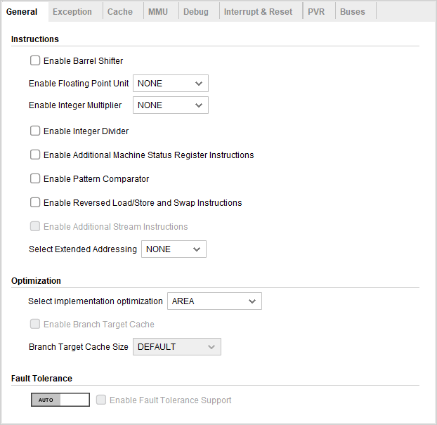
Enable Barrel Shifter
Enabling the barrel shifter adds support for multi-bit shift instructions. Those additional instructions have a one cycle latency with performance or frequency optimization or a two-cycle latency for area optimization. This option also enables bit field manipulation instructions. Without the barrel shifter shifts have to be performed one bit at a time. This considerably slows down multi-bit shifts which must be implemented using either an unrolled loop of shift instructions or a short loop. The addition of the barrel shifter increases the resource usage of the MicroBlaze meaning the feature must be weighed against the performance improvement it offers.
Shifts are usually quite common, even in general purpose routines and drivers. And for some applications that frequently encode and decode data, they can be critical to the overall performance. For example, a networking stack or a file system could contain a considerable number of shifts. Consequently it is usually recommended to include the barrel shifter for acceptable performance.
Enable Floating Point Unit
Apart from disabled, the MicroBlaze floating point unit comes in two flavours “Basic” and “Extended”. Basic contains all the usual arithmetical operations while Extended adds the conversion and square root instructions. Enabling the FPU does add to the size of the MicroBlaze significantly, as such it is best suited for applications that relies heavily on floating points. From an RTOS perspective, it is rare for RTOSes to use floating points. One interesting aspect of the MicroBlaze FPU is that general purpose registers are used instead of a dedicated register bank. This means that apart from an additional status register, enabling the FPU doesn’t significantly affect the context switch overhead. This is in contrast with most MCU and MPU which use a, sometimes very large, dedicated register banks which have to be saved and restored between context switches.
Note that for thread safety, the MicroBlaze port of the chosen kernel must have support for the MicroBlaze FPU.
Enable Integer Multiplier
Rather self-explanatory, the integer multiplier adds 32 and, optionally, 64 bit integer multiplication instructions. This gives a rather significant boost to applications relying on multiplications. The multiplier is also quite cheap resource-wise but does use three or four DSP slices. As such, unless DSP slices are in short supply it is recommended to activate the multiplier. As far as RTOS components go multiplications are not used that often. However they can be used in some rather critical code path. One example is time conversion, especially from the raw kernel tick rate to milliseconds and vice-versa can benefit from a hardware multiplier.
Enable Integer Divider
Similar to the multiplier, this option adds support for hardware integer division. This one consumes more resources than the multiplier. As such it is rather application specific whether hardware division should be included or not. Again, time conversion can be fairly reliant on fast integer division, although that depends on how they are implemented.
Enable Additional Machine Status Register Instructions
This configuration option adds the MSRSET and MSRCLR instructions, which can set or clear one of more bits in the status register in a single cycle. This can greatly improve the performance of critical sections or, in other words, enabling and disabling interrupts which is rather frequent when using an RTOS. This option is recommended when running with an RTOS.
Note that for the performance improvement to be seen a kernel’s implementation for the MicroBlaze must be written to use the MSRSET/CLR instructions. Similarly, some kernels may require those instructions to be present in all cases.
Enable Pattern Comparator
The pattern comparator speeds up some pattern matching operations such as string compare, flag setting and checking. This option also adds the count leading zero instruction, often used by kernels for priority decoding. The pattern comparator doesn’t use much resource and is recommended to improve kernel scheduling performance.
Note that the kernel must support the CLZ instruction to see the scheduling performance improvement.
Enable Reversed Load/Store and Swap Instructions
This option enables quick endianness conversion useful with a network stack or a big-endian file system. It is also very cheap so it is recommended if byte swapping is useful.
Enable Additional Stream Instructions
This option only add instructions useful to manipulate the optional AXI stream links. Those instructions are mostly system specific and are not used by general purpose RTOS software.
Select Extended Addressing
This option enables address extension beyond the 32-bit limit of 4 GiB. This is rarely used with simple RTOSes and requires special support within the kernel to be usable. For the 64-bit MicroBlaze this selects the accessible address range.
Select Implement Optimization
This is the same option as the one found in the Configuration Wizard.
Branch Target Cache
The branch target cache adds a dynamic branch prediction scheme to the MicroBlaze, the Branch target cache will save branches target address and instruction allowing a correctly predicted branch to be executed in a single cycle. When enabled, an additional option becomes available to configure the size of the cache. The default value is set to use only a single block RAM when the address sizes are 32 bit. From 64 entries and under the branch target cache is implemented using distributed RAM. Note that there are a few mistakes in the tooltip and BRAM calculation inside Vivado. The default value that uses one block RAM is 512 entries not 1024. Also if 512 entries is selected explicitly, the calculated number of block RAM for the branch target cache is two but only one will be used in the final implemented design.
The branch target cache uses quite a lot of FPGA resources so is best reserved for high-end applications. However RTOS code and application can benefit from the improved performance. Enabling the branch target cache can also slightly improve the maximum achievable frequency of the MicroBlaze.
Exception
The “Exception” configurations enable various optional exception handlers available to the MicroBlaze.
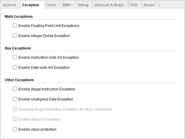
Enable stack protection
The stack protection feature can be used by real time kernels to detect stack overflows and underflows at runtime. This can be very useful for debugging or even in production for an added layer of safety.
For this feature to work additional stack handling steps must be done by the kernel during context switches. As such it’s important to make sure that the chosen kernel supports this feature otherwise the application will fail on the first context switch.
Cache
The cache panel will be discussed in the next article on the MicroBlaze.
MMU
The MMU pane contains the various configurations for the optional MicroBlaze MMU.
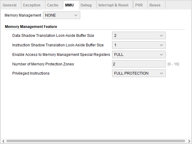
There are multiple options for the MMU implementation. The first one, USERMODE, isn’t really an MMU but enables a privileged and non-privileged state for the MicroBlaze. Protection offers memory protection but no virtual memory capabilities. This would be similar to a Memory Protection Unit as found in other microcontrollers. Finally, the VIRTUAL implementation enables all the features expected from an MMU including access protection and memory address translation.
The MMU will usually be used by the RTOS, so the choice of adding one depends on the chosen RTOS. However it is possible to configure the PROTECTION or VIRTUAL mode with a static mapping offering basic protection for different memory regions. Enabling the MMU significantly increases the MicroBlaze size and reduce the maximum achievable frequency so the MMU should be reserved for applications that really need it.
Debug
The Debug section controls the various debugging features of the MicroBlaze.
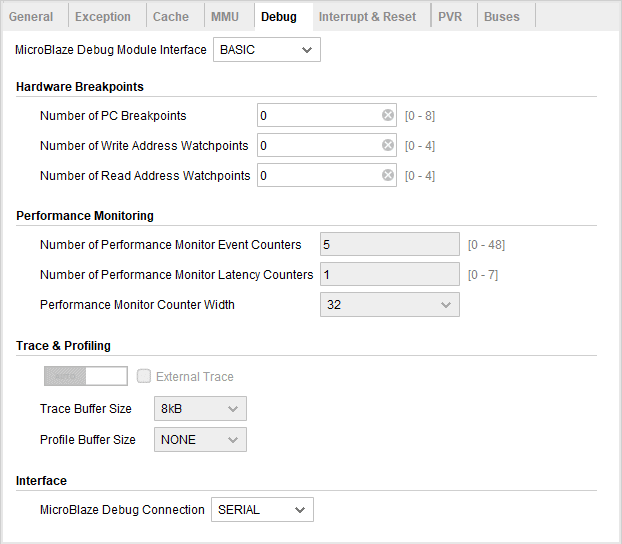
Usually, the RTOS and application do not interact directly with the debug feature, as such those configurations are mostly directed by the development needs. It is, however, important to note that most of the debugging options carry a significant cost in resources and maximum frequency. As such, the selected features should be kept conservative.
Interrupt & Reset
The Interrupt & Reset panel contains the configuration of the MicroBlaze interrupt request line as well as the reset value of the MSR and vector base address registers.
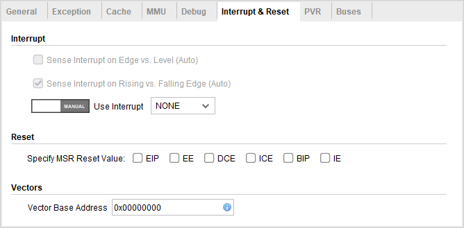
Most of those settings should not usually be touched as they will break compatibility with existing code and peripherals. The interrupt type FAST enables an auto-vectored interrupt processing where an ISR is called (jumped to) by the CPU instead of a common interrupt handler. It’s important the interrupt management code as well as the kernel support the FAST mode if selected.
PVR
The PVR section configures the Processor Version Registers which can be used by an application or RTOS to query the version, implemented features and many configuration options for the MicroBlaze.
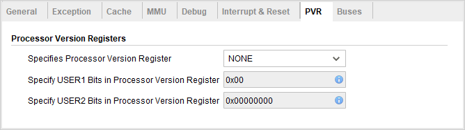
Unless required by the application or RTOS the PVR registers are not needed and should be kept disabled.
Buses
Finally, the last configuration panel is to configure all the MicroBlaze buses.
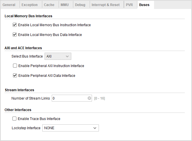
The buses configuration has more to do with the memory hierarchy of the MicroBlaze, as discussed in part 1 of this series. The choice of where code and data reside will obviously affect performance and resource usage but is mostly transparent to the software. The location of code and data will, however, affect the ideal cache configuration which will be covered in the next article.
Click here for the third part of this series looking at the cache configuration for the MicroBlaze in detail.
Questions or comments?
Do not hesitate to contact us at blog@jblopen.com. Your questions, comments and, suggestions are appreciated.